音ノ木坂学院

叶え!みんなの夢――

0%

LinkNode D1 评测与使用

本文原文发表在《无线电》上,感谢fm老师提供开发板和指导

LinkNode D1 简介

LinkNode D1是LinkSprite公司出品的一款Arduino兼容的WiFi开发板。ESP-8266EX 使用 Tensilica L106 32 bit 为MCU,这款MCU主要特点有:

  • 支持802.11 b/g/n标准
  • 支持WPA/WPA2
  • 支持STA/AP/STA+AP 三种工作模式
  • 唤醒到开始传输数据时间小于2 ms
  • 待机功率小于1.0 mW

这些特性使得LinkNode D1可以以低功耗模式、在多种WiFi环境下运行。此外,LinkNode D1的开发板还在此基础上扩展了以下功能:

  • 11个数字IO口
  • 1个模拟输入口
  • 1个Micro USB口用于供电和UART数据传输
  • 1个9~24V供电口
  • 4M Flash
  • 80K 内存

这使得LinkNode D1可以连接更多的传感器等元件,也可以支持更复杂的代码。
LinkNode D1的串口转USB使用的是CH340,它提供了Windows、Mac和Linux的驱动,使得这款LinkNode D1可以在多平台上进行开发。

使用Arduino模式开发

LinkNode D1在Arduino Studio的库比较完善,环境配置也比较简单,适合刚开始接触LinkNode D1的用户快速熟悉其特性或开始工程。使用Arduino Studio进行开发的方式如下。

Arduino Studio开发环境搭建

首先下载并安装Arduino Studio,运行程序。在“文件”菜单中打开首选项。如下图所示,在“附加开发版管理器网址”一栏里添加如下网址以获得ESP-8266EX的有关参数:
http://arduino.esp8266.com/stable/package_esp8266com_index.json。如果已经添加过其他网址,用逗号隔开多个网址。

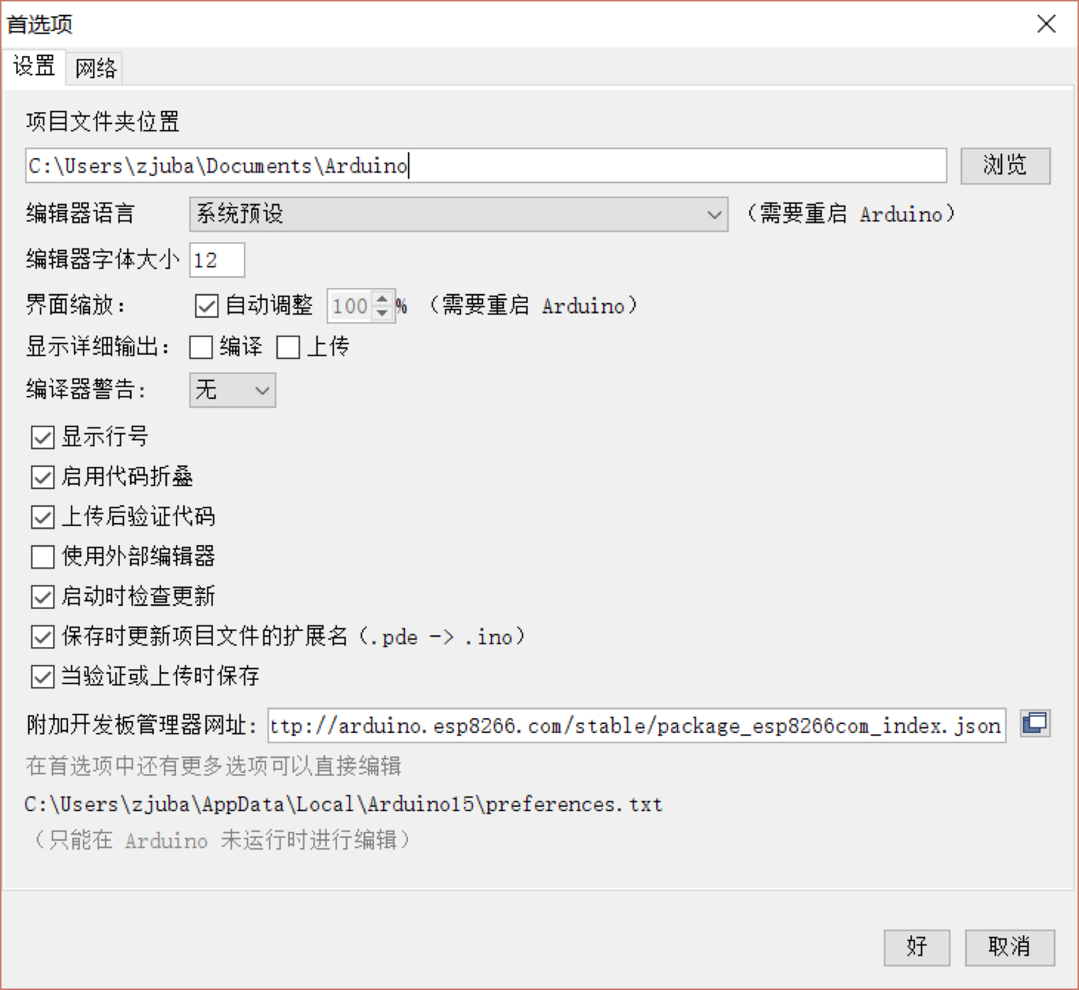
保存后打开“工具”->”开发板”->“开发板管理器”,在弹出的开发板管理器窗口里搜索“esp8266”,选择一个版本进行安装。

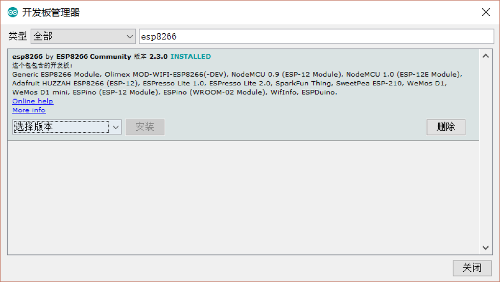
安装完开发板信息后,再打开“项目”->“加载库”->“管理库”,在库管理器窗口里搜索“wifimanager”,点击安装。

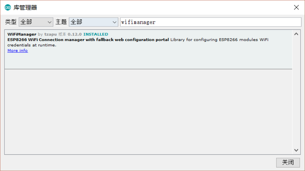
最后在“工具”菜单里选择开发板为“WeMos D1 (Retired)”,CPU Frequency为80 MHz,Flash Size为“4M (3M SPIFFS)”,Upload Speed为921600,并选择对应的串口。至此,开发环境配置完成。
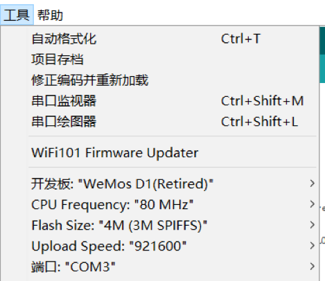
编写烧录程序

在不外接扩展设备的情况下,LinkNode D1与用户的主要交互手段有两个,一是ESP-8266芯片上的LED灯,二是串口。接下来先写一个最简单的程序,实现LED灯闪烁和串口发送“Hello, World!”。

1
2
3
4
5
6
7
8
9
10
11
12
void setup() {
// initialize digital pin GPIO2/D9 as an output.
pinMode(BUILTIN_LED, OUTPUT);
Serial.begin(115200);
}
void loop() {
digitalWrite(BUILTIN_LED, HIGH); // turn the LED on (HIGH is the voltage level)
delay(1000); // wait for a second
digitalWrite(BUILTIN_LED, LOW); // turn the LED off by making the voltage LOW
delay(1000); // wait for a second
Serial.println("Hello world!");
}

点击Arduino Studio上的上传按钮将文件上传到开发板上。之后打开“工具”->“串口监视器”,在右下角将波特率设置为115200。可以看到,开发板上的灯开始闪烁,并能在串口监视器中看到“Hello, World!”。

使用WiFi Manager连接到路由器

ESP-8266EX提供的WiFi Manager库可以使芯片很容易通过无线AP接入互联网。因为其支持AP模式和SAT模式,所以思路是先让LinkNode作为无线AP,待其他移动设备连接到无线AP后,通过LinkNode的管理页面选择SSID并输入密码,最后LinkNode再以STA模式接入选定的无线AP,从而连入互联网。
在Arduino Studio中修改代码如下:

1
2
3
4
5
6
7
8
9
10
11
12
13
14
15
16
#include <ESP8266WiFi.h>          //https://github.com/esp8266/Arduino
#include <DNSServer.h>
#include <ESP8266WebServer.h>
#include <WiFiManager.h> //https://github.com/tzapu/WiFiManager

void setup() {
Serial.begin(115200);
WiFiManager wifiManager;
wifiManager.setAPStaticIPConfig(IPAddress(10,0,1,1), IPAddress(10,0,1,1), IPAddress(255,255,255,0));
wifiManager.autoConnect("LinkNodeAP");
Serial.println("connected... :)");
}

void loop() {

}

点击上传后,使用手机搜索WiFi,可以看到LinkNodeAP的SSID。连接并进入配置界面http://10.0.1.1/,如图所示:

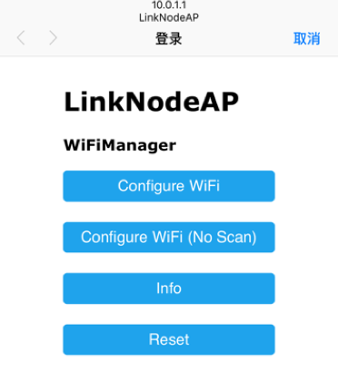
点击Configure WiFi,LinkNode会搜索附近的WiFi,同时在串口和手机网页输出AP信息。输入SSID和密码接入网络,这些信息会被存储,除非在代码里调用用wifiManager.resetSettings() 清除配置。

接入网络后,串口监视器里也可以看到提示。
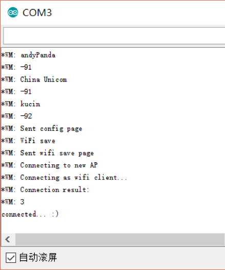
使用NodeMCU模式开发

NodeMCU使用脚本语言Lua为ESP8266直接编写固件,由于其轻量、接口封装好等特点受到开发者很大欢迎。这款LinkNode D1也支持使用NodeMCU直接向ESP8266刷写程序。使用NodeMCU的方式如下。

刷写

首先使用NodeMCU Flasher刷写,波特率设置为9600(可以修改为别的速率)。然后选择端口,点击刷写。在9600的速度下刷写过程需要大约5分钟,耐心等待完成。

上传程序

NodeMCU有多种方式上传程序,这里选用使用Java编写,支持跨多平台的ESPlorer

  1. 将LinkNode D1连接到电脑上并运行ESPlorer.jar
  2. 在ESPlorer右侧点击刷新按钮,选择LinkNode D1对应的串口号,点击Open打开串口。如果此时Open状态灯为红色,按下LinkNode D1上的reset按钮,状态灯转绿后可以继续操作
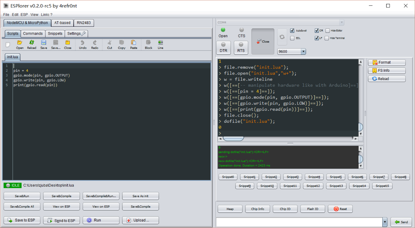
  3. 新建一个init.lua,使ESP8266上的LED常亮,代码如下所示
    1
    2
    3
    4
    5
    -- init.lua
    pin = 4
    gpio.mode(pin, gpio.OUTPUT)
    gpio.write(pin, gpio.LOW)
    print(gpio.read(pin))
  4. 点击左下角的Save to ESP,等待上传完成后可以看到,LED灯被点亮

连接到路由器

修改init.lua,输入如下内容。设置WiFi模式为STATION。输入所在环境下无线路由器的SSID和密码,连接到路由器上。

1
2
3
4
5
6
7
8
9
10
11
12
13
14
15
16
17
18
19
20
21
22
23
24
25
function startup()
if file.open("init.lua") == nil then
print("init.lua deleted or renamed")
else
print("Running")
file.close("init.lua")
-- the actual application is stored in 'application.lua'
-- dofile("application.lua")
end
end

print("Connecting to WiFi access point...")
wifi.setmode(wifi.STATION)
wifi.sta.config("SSID", "PASSWORD")
tmr.alarm(1, 1000, 1, function()
if wifi.sta.getip() == nil then
print("Waiting for IP address...")
else
tmr.stop(1)
print("WiFi connection established, IP address: " .. wifi.sta.getip())
print("You have 3 seconds to abort")
print("Waiting...")
tmr.alarm(0, 3000, 0, startup)
end
end)

点击Save to ESP,等待文件上传完成。Init.lua会在启动时被自动加载运行。这时可以看到,LinkNode已经连接到了无线路由器上,并取得了IP地址。

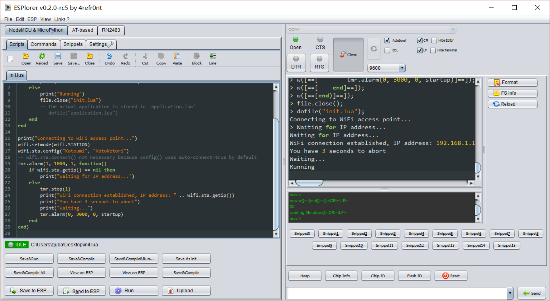
此时重新刷写其他程序不会影响WiFi连接。

使用LinkSprite IO云平台

LinkSpritIO 是LinkSprite公司开发的云平台,支持RESTful API和WebSocket,可以实现网页/桌面/移动端对LinkNode等IoT设备的控制和信息交互。
在LinkSpritIO中,所有数据包都以JSON格式存储,通过HTTP传输。其提供了两套API,分别供IoT设备和其他设备使用,所有API都支持Update和Query操作。用户除了使用API,也可以在LinkSprite IO的网页上直接对数据进行查询和修改。
LinkSprite IO的使用非常简便。先在其网站注册账号,注册后点击“My Profile”,可以看到一个API Key。再点击“My Device”,选择“Create New Device”,“Device Type”选择“Simple Light“,之后可以看到一个Device ID。API Key和Device ID是区别不同设备的重要标识。
到这里,LinkSPrite IO上的工程就建立完成了,接下来编写LinkNode D1上的程序。以Arduino Studio开发模式为例,使用刚刚已经连接到互联网上的开发版,修改代码如下:

1
2
3
4
5
6
7
8
9
10
11
12
13
14
15
16
17
18
19
20
21
22
23
24
25
26
27
28
29
30
31
32
33
34
35
36
37
38
39
40
41
42
43
44
45
46
47
48
49
50
51
52
53
54
55
56
57
58
59
60
61
62
63
64
65
66
67
68
69
70
71
72
#include <ESP8266WiFi.h>
#include <WString.h>
//the library are needed for autoconfig WiFi
#include <DNSServer.h>
#include <ESP8266WebServer.h>
#include <WiFiManager.h>
// replace with your own API key and device ID,

String apikey = "xxxxxxxxxxxxxxxxxxxxxxxxxxxx";
const char* deviceID="xxxxxxxxxxxxx";
const char* server = "www.linksprite.io";
WiFiClient client;

void setup() {
Serial.begin(115200);
pinMode(BUILTIN_LED, OUTPUT);
WiFiManager wifiManager;
wifiManager.setAPStaticIPConfig(IPAddress(10,0,1,1), IPAddress(10,0,1,1), IPAddress(255,255,255,0));
wifiManager.autoConnect("LinkNodeAP");
Serial.print("WiFi Connected ...\n");
Serial.println("WiFi connected");
}

void loop() {
if (client.connect(server,80)) {
String postStr ="{";
postStr +="\"action\":\"query\",";
postStr +="\"apikey\":\"";
postStr += apikey;
postStr +="\",";
postStr +="\"deviceid\":\"";
postStr += deviceID;
postStr +="\",";
postStr += "\"params\":";
postStr += "[";
postStr += "\"light\"";
postStr +="]";
postStr +="}";
client.print("POST /api/http HTTP/1.1\n");
client.print("Host: ");
client.print(server);
client.print("\nContent-Type: application/json\n");
client.print("Content-Length: ");
client.print(postStr.length());
client.print("\n\n");
client.print(postStr);
}
delay(1000);
Serial.println("Store response...");
String request = "";
while (client.available()) {
char c = client.read();
request +=c;
}
if (request != NULL) {
int index1 = request.indexOf(":{");
int index2 = request.indexOf("},");
String param = request.substring(index1, index2 + 1);
Serial.print("The param is ");
Serial.println(param);
if(param.indexOf("off")>0) {
digitalWrite(BUILTIN_LED, HIGH);
Serial.println("OFF");
} else if(param.indexOf("on")>0) {
digitalWrite(BUILTIN_LED, LOW);
Serial.println("ON");
}
client.stop();
Serial.println("Waiting...");
delay(2000);
}
}

这段程序里构造了HTTP请求并以POST方式发送给LinkSprite IO,同时接受返回的信息。如果使用NodeMCU模式开发,则使用conn模块发送HTTP请求,同理可以达到这一效果。
上传到开发板后,在LinkSprite IO的页面里点击Light On或Light Off并点击Save,这个Device里的json的值会发生变化。LinkNode D1通过网络读取到json的变化,并据此改变LED等的状态。

有了API Key和Device ID,用户也可以在其他程序中通过发送HTTP请求来完成对LinkNode设备的控制。通过支持LinkSprite API的Gateway,还可以将应用范围扩展到Bluetooth、ZigBee等其他设备上。


软文总结部分就不发啦,想看原文可以去买杂志~

以及截止本文测试的时候,CH340仍然 没有 一个Apple官方支持的驱动,如果直接安装其官网提供的mac驱动并连上USB就会报kernel panic,导致系统重置,需要小心。建议最好在Windows平台下使用该开发板。